
By Inverting vs Non-Inverting Amplifiers 2714
What Is an Inverting Amplifier?
What Is a Non-Inverting Amplifier?
Key Differences: Focus on the Essentials
Pros and Cons: Choose What Fits
Performance Battle: Data Tells the Truth
Application First: Which One Is Best for You?
Hands-On: Build and Test Guide
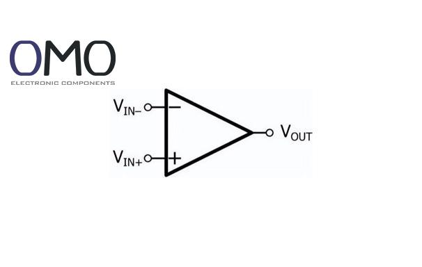
An inverting amplifier is a basic operational amplifier (op-amp) circuit. The input signal goes into the inverting input (negative terminal) of the op-amp. The main feature is that the output signal is opposite in phase to the input. This kind of circuit is useful when phase inversion is needed, such as in sensor signal conditioning.
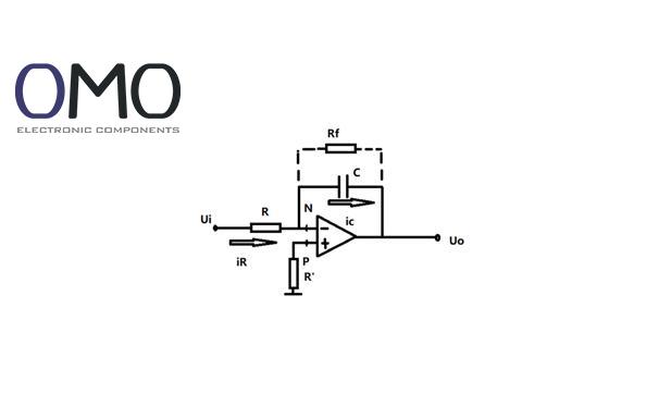
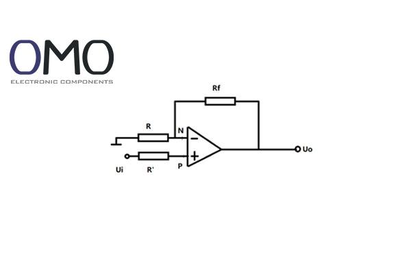
The input signal goes through an input resistor into the inverting terminal. The op-amp uses its very high open-loop gain, along with a feedback resistor, to force the inverting terminal to act like a virtual ground. The output signal returns to the inverting input through the feedback resistor, creating a deep negative feedback loop. This structure controls the voltage gain and keeps the operation stable.
The basic circuit includes an op-amp, input resistor (Rin), and feedback resistor (Rf). The non-inverting terminal is grounded to give a reference voltage. The input signal is applied between Rin and the inverting terminal. Rf connects the output to the inverting terminal. This is a simple setup, ideal for beginners.
A non-inverting amplifier connects the input signal to the non-inverting input (positive terminal) of the op-amp. The output signal has the same phase as the input. It is a good choice for voltage followers or non-inverting gain circuits, especially in applications like impedance matching to protect weak signal sources.
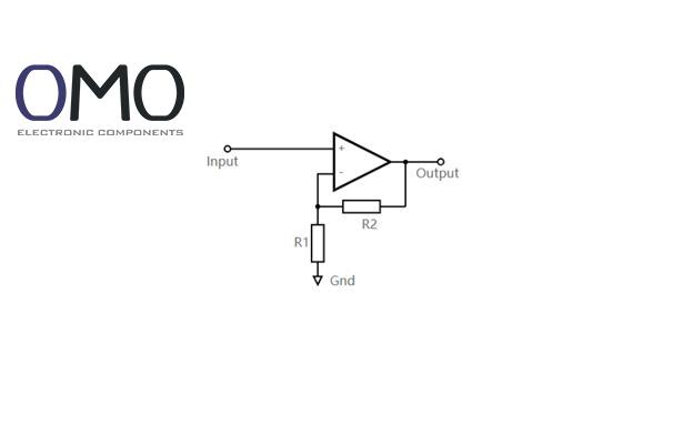
The input signal directly drives the non-inverting terminal. The feedback path (Rf connects output to the inverting terminal, and the inverting terminal connects to ground through resistor R1) sets a stable operation point and precise gain. The virtual short property makes the inverting terminal follow the voltage at the non-inverting terminal. So, the output follows the input signal closely.
The key parts include an op-amp, the input signal connected to the non-inverting terminal, feedback resistor (Rf), and ground resistor (R1). Rf goes from the output to the inverting terminal, and R1 connects the inverting terminal to ground. Unlike the inverting amplifier, the signal source is not grounded, so there’s less load on the input.
Big difference:
The output phase follows the gain sign: inverting amplifier gives an inverted output, while the non-inverting amplifier gives an in-phase output. If your application needs strict phase matching, the non-inverting type is better.
| Pros | Cons |
| Simple circuit design | Low input impedance (≈ Rin) |
| Flexible gain setting (Av = -Rf/Rin) | Output signal is inverted |
| Virtual ground helps reduce noise | Resistor values affect source loading |
Pros:
Cons:
Both circuits' bandwidth is limited by the gain-bandwidth product (GBW) of the op-amp. Imagine a frequency response graph:
Each curve starts with different gain levels and drops at -20 dB/decade. They cross at the GBW point. The inverting type may be more stable at high frequencies due to slightly higher loop gain.
Thanks to negative feedback, both circuits are highly linear in their operating range. The op-amp model and closed-loop gain determine the accuracy. XX Electronics’ high-precision op-amp Δ (±0.001%) greatly improves linearity.
Power usage depends on the op-amp’s static current and resistor values. For low-power design, choose low quiescent current op-amps and avoid very small resistors (which increase current). XX Electronics chips provide full performance with <1mA current.
High? → Non-inverting
Low? → Either
Need gain <1? → Inverting
Must keep same phase? → Non-inverting
Need summing? → Inverting
Sensitive to common-mode noise? → Use non-inverting with high CMRR op-amp
Check if power is on and voltage is correct
Check op-amp pin connections
Measure static voltage at input/output
Check resistor values again
Inspect connection points
Add 0.1μF ceramic capacitors near power pins
Keep feedback wires short
Add small capacitor (a few pF to tens of pF) across Rf to compensate
You can differentiate inverting and non-inverting operational amplifier (op-amp) configurations by their phase shift: the output of an inverting amplifier is 180° out of phase with the input, while the output of a non-inverting amplifier is in phase (0° shift) with the input.
The inverting amplifier, a core op-amp circuit, produces an amplified output signal that is phase-shifted by 180° relative to its input signal.
An inverting amplifier boosts the input signal but reverses its phase (providing a 180° shift). Its functions include changing signal amplitude, setting gain levels, and preparing signals for numerous applications.
The non-inverting amplifier, a fundamental op-amp circuit, boosts the input signal's amplitude without altering its phase (resulting in 0° phase shift).