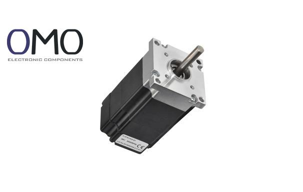
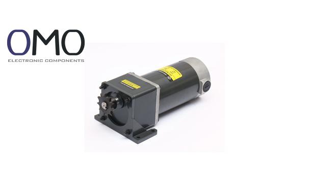
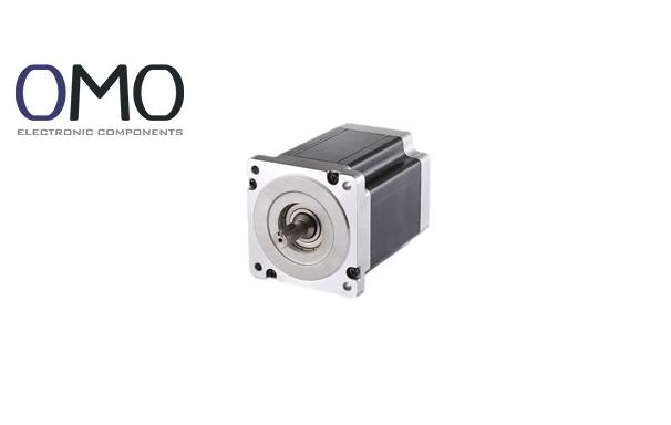
A DC motor (Direct Current Motor) is an electromagnetic device. It changes direct current (DC) electrical energy into continuous rotating mechanical energy. It is one of the oldest and most widely used power sources since the Industrial Revolution. Its design uses the interaction of electricity and magnetism to produce useful motion.
Function
The main function is to drive different mechanical loads. It can provide adjustable speed and torque (rotational force). This meets different needs for starting, running, and speed control. For example, it moves materials on conveyor belts or gives strong torque in power tools.
Structure
The DC motor uses a classic rotating design. The fixed part (stator) makes a magnetic field. The moving part (rotor) rotates when electricity flows through it. The motor uses a commutator to send current into the rotor. Electromagnetic force keeps the rotor spinning. The motor is compact. Key parts work closely around the central shaft.
Basic Principle
The motor works based on Faraday’s Law of Electromagnetic Induction and Fleming’s Left-Hand Rule. When current flows through a conductor in a magnetic field, it feels a force (Lorentz force). This force pushes the rotor, creating continuous rotation.
Main Parts
Stator: Creates a stable or controllable magnetic field. It may use rare earth magnets (like neodymium).
Rotor (Armature): Includes a laminated iron core, armature winding, and shaft. It changes electric energy to motion.
Brushes: Made of carbon graphite. They send electricity to the rotating rotor.
Commutator: Made of copper segments. It rotates with the rotor and touches the brushes. It switches current direction at the right time to keep the rotor turning one way.
Housing: Supports and protects the motor. Also helps cool it.
End Covers and Bearings: Hold the rotor in place and help it rotate smoothly.
Features
Advantages: Simple structure, high starting torque (especially in series type), very smooth and linear speed control (by changing voltage or field current), mature control technology, low cost, and high reliability.
Disadvantages: The brush and commutator wear out and make sparks (especially at high speed or current), need regular maintenance. Sparks may be dangerous in flammable places. Compared to AC motors with variable frequency drives, efficiency is a bit lower under the same power. Power density is usually lower than modern AC motors.
Working Principle
Electromagnetic Principle
The key idea is that a conductor with current in a magnetic field feels a force (Lorentz force). When DC current goes through the armature winding on the rotor, it becomes a current-carrying wire. The stator’s magnetic field and the current interact. This makes opposite electromagnetic forces on both sides of the winding. These forces make torque that rotates the rotor.
Operation Process
Power Supply: External DC power enters through brushes into the commutator.
Current Flow and Switching: The commutator connects to different armature coils. As the rotor turns, different commutator segments touch the brushes. This sends current to the best-positioned coil and changes the direction in others.
Continuous Rotation: The current in the windings keeps switching direction. It works with the stator field to make torque in one direction. The rotor keeps turning. The brushes and commutator work like a smart “water switch,” always pushing the “water wheel” (rotor) in the right way.
Armature Reaction and Commutation
Armature Reaction: When the motor runs with load, the rotor also makes its own magnetic field. This field distorts the stator’s field, especially near the poles. This can shift the neutral zone, reduce performance, and cause problems with commutation. Good design (like compensation windings or advanced field control by XX Technology) helps reduce this effect.
Commutation Process: This is the moment when a winding changes from one commutator segment to the next. The current switches direction (positive to negative or opposite). Perfect commutation means no spark. But in real use, winding inductance slows current change. This causes voltage spikes and sparks between brush and commutator. To reduce this, engineers use better commutator shapes and special brush materials (like XX Technology’s low-noise formula).
Energy Conversion
The DC motor is a smart energy converter:
Input = electric power (Voltage U × Current I)
Output = mechanical power (Torque T × Speed n)
Power balance:
P_elec = U × I ≈ T × ω + total losses (ΣP_loss), where ω = 2πn / 60
Most energy changes happen in the rotor:
electric input → magnetic energy in windings → electromagnetic torque → mechanical energy at shaft
Performance and Characteristics
Speed-Torque Characteristic
The speed-torque (n-T) curve is very important. It looks like a gentle downward line:
At startup (speed = 0), it gives the highest starting torque (Ts).
As speed increases, torque goes down.
At no load, it reaches the highest speed (n0).
The slope depends on internal resistance and excitation method.
Series motors have steep curves (high torque but risky overspeed when unloaded).
Shunt and permanent magnet motors have flatter curves (stable speed).
Efficiency and Power
Efficiency η = (Output power / Input power) × 100%
DC motors usually have 70%-90% efficiency. It depends on type, size, load, and design.
Small motors are less efficient. Large ones are better.
Permanent Magnet DC (PMDC) motors work well in light-load high-efficiency uses.
Best efficiency happens at 75%-100% load.
Output = UI − ΣP_loss = Tω
Dynamic Response
DC motors respond fast because:
Electromagnetic torque comes directly from voltage or current.
Output torque/speed has a linear relationship with input.
So DC motors start quickly (can take large current for a short time), brake fast (regenerative or resistive braking), and change speed quickly. They are good for precise speed control and frequent start-stop use.
Loss Analysis
Main losses include:
Copper Loss (I²R): Heat from current in windings. Main loss.
Core Loss (Iron Loss): Magnetic losses in stator/rotor from changing magnetic field.
Stray Loss: From winding layout, magnetic imbalance, or harmonics.
Application Scenarios
Industrial Field
DC motors (Direct Current Motors) are the foundation of industrial automation:
They drive conveyor belts, assembly lines, hoists, and elevators (especially where smooth speed control and positioning are needed).
They provide precise feed motion and spindle drive for machine tools (such as drilling machines, milling machines, grinding machines, and lathes), and allow stepless speed control.
They drive mixers, extruders, pumps, and fans (helping save energy with wide-range speed control).
Transportation and Automotive
Electric vehicle drive (used widely in the past; now partly replaced by advanced AC solutions, but still used in some areas).
Core power of car starter systems (provides instant high torque).
Drives for wipers, seat adjusters, sunroofs, and power windows (mostly using Permanent Magnet DC Motors, PMDC).
Drive motors for forklifts and electric tractors (valued for good starting performance).
Metro and tram traction drive systems (high-power DC drive systems).
Consumer Electronics
Power for toy cars and RC (Remote Control) models.
Home appliances: fan motors, juicers, blenders, shavers, and electric toothbrush vibrators.
Office devices: printer paper feed/scanning drive, copier toner systems, early hard drive spindle drives.
Renewable Energy Systems
Drive actuators for yaw (wind direction control) and pitch (blade angle control) in small wind turbines.
Solar panel tracking devices for sun azimuth and elevation.
Actuator drives for renewable system support equipment (like pressure relief valves and cooling pumps).
Special Environment Applications
Medical devices: electric beds, infusion pumps, ventilators, and electric wheelchair drives (require high reliability, quietness, and smooth operation).
Industrial robots: control joint motion precisely (still used where fast response, small size, high torque density, and direct control are needed, along with high-performance servo drives).
Precision instruments: used where fine speed control and positioning are needed.
Advantages, Disadvantages, and Maintenance
Advantages
Smooth, linear, wide-range speed control: You can easily adjust speed by changing armature voltage or (for brushed motors) excitation current. Control is simple and low-cost.
Excellent starting performance: Naturally high starting torque, good for heavy load starting (like cranes or starters).
Cost-effective: Traditional DC motors (especially brushed types) usually have lower initial and control costs than complex variable-frequency induction motors.
Direct torque control: Torque is almost linear with armature current. It is easy to apply current (torque) closed-loop control with fast response.
Disadvantages
High maintenance needs (for brushed motors): Brushes and commutators wear out and are weak parts. You must inspect and replace brushes regularly and clean commutator grooves. This takes time and cost.
Sparking and electromagnetic interference (EMI): Commutation causes unavoidable sparks. These can be fire/explosion risks and produce EMI that may affect nearby devices.
Lower efficiency: Especially in brushed motors, contact resistance and commutation losses reduce efficiency compared to optimized AC motor systems.
Speed limits and noise: At high speed, commutation is harder. Wear, sparks, and noise increase.
Power and speed limits: Commutation ability, heat, and mechanical strength limit large power and high speed. Brushless motors are preferred for such uses.
Maintenance Requirements
To keep DC motors (especially brushed types) running reliably:
Regular check and cleaning: Use dry compressed air to remove dust and carbon powder. Keep ventilation clear. Check appearance and wiring.
Brush maintenance: Check brush length (should not be shorter than 1/3 of original or specified value), wear uniformity, movement, and spring pressure. Replace worn brushes (in pairs), and “run in” new brushes.
Commutator care: Use fine sandpaper (non-metallic) to clean light oxide or burn marks. If grooves (mica slots) are filled with carbon, use a hook knife to clean (cut down about 0.5–1.5mm). Keep surface smooth and round.
Bearing lubrication: Follow maker’s guide to add or replace grease on time. Listen for unusual sounds.
Electrical connections: Tighten terminals. Make sure there’s no looseness, overheating, or oxidation. Measure insulation resistance (usually > 1 MΩ).
Operation monitoring: Watch temperature, vibration, and noise for changes.
Common Faults and Fixes
Severe sparks or ring fire: May be caused by worn brushes, dirty/damaged commutator, shorted/ broken windings, wrong field polarity, or unstable loads. Fix: stop motor, inspect and repair parts, keep good ventilation, avoid overloading.
Overheating: Could come from overload, blocked airflow, fan failure, brush pressure too high, big sparks, winding problems, bearing damage, poor lubrication, or hot surroundings. Fix: reduce load, clean vents/replace fan, adjust brushes, fix windings, replace bearings, improve cooling.
Unstable speed or no start: Causes include wrong voltage, open circuits, bad contacts, brush issues, shorted windings, starter failure, or jammed load. Fix: check power, wiring, brushes, windings, and mechanical parts.
Abnormal mechanical noise: Can come from bad bearings (replace), rotor scraping (fix shaft), loose parts (tighten), or fan rubbing (adjust). Fix: locate noise and replace or repair parts.
Abnormal electrical noise: Sharp brush sounds (check brush fit and pressure), or loud humming (may be unbalanced excitation). Fix: inspect brushes and field current.
Low output power: May be due to low voltage, weak field (demagnetized magnets or low excitation), high armature resistance (bad contacts), or extra friction. Fix: measure voltage/current, check brushes and contacts, inspect mechanical parts.
Motor Type Overview
Permanent Magnet DC Motor (PMDC)
Definition and Structure: The stator uses permanent magnets (like NdFeB or ferrite) to create a fixed field. The rotor is a regular armature with brushes and a commutator. This is the most common brushed DC motor today.
Features and Applications:
Simple and compact structure, small size and light weight.
High efficiency (especially under light/medium loads).
Easy control (just control armature voltage).
High starting torque and good speed control.
Downsides: Cannot use field weakening to speed up. High-power magnets are costly (rare earth).
Applications: Small car motors (except starters), home appliances (fans, toys), office devices, models, and small to medium industrial uses.
Shunt Wound DC Motor
Definition and Structure: The field winding (excitation coil) is connected in parallel with the rotor armature. It can also use separate power supplies (separately excited).
Features and Applications:
"Hard" speed feature: With constant field current (at fixed voltage), speed drops only slightly when load increases. Speed control uses voltage (below base speed) or weakening field (above base speed).
Medium starting torque (about 125–200% of rated torque).
Easy voltage control on main circuit.
Applications: Good for constant-speed needs, like machine tools, centrifugal pumps, fans, conveyors.
Series Wound DC Motor
Definition and Structure: The field and armature windings are in series.
Features and Applications:
Very high starting torque: Startup current is big, making the magnetic field strong. Starting torque can be over 500% of rated value.
"Soft" speed feature: No-load speed can be extremely high (dangerous runaway), speed drops fast as load rises.
Speed control by voltage or added resistors (but less efficient).
Applications: Places needing strong starts, like cranes, starters, traction motors (especially on slopes), rolling doors.
Compound Wound DC Motor
Definition and Structure: Has both shunt and series windings (sometimes on the same pole). Two types:
Cumulative compound (series field helps main field – common)
Differential compound (series field opposes main field)
Features and Applications:
Combines shunt and series benefits: Higher starting torque than shunt, but more stable than series.
Speed-torque curve is between shunt and series types.
Flexible use, tunable for need.
Applications: Equipment that needs both strong starting and stable speed, like stamping machines, compressors, elevators.
Key Differences Between Motor Types
Feature
PMDC
Shunt DC
Series DC
Compound DC (Cumulative)
Field Type
Permanent Magnet
Shunt winding
Series winding
Both shunt and series windings
Start Torque
High (250–400% Tn)
Medium (125–200% Tn)
Very High (>500% Tn)
High (250–400% Tn)Start Torque
Speed Behavior
Hard (slight drop)
Hard
Very soft
Semi-hard
No-load Risk
Safe (limited speed)
Safe
Dangerous (runaway)
Safe
Speed Control Method
Armature voltage
Voltage + field weakening
Voltage + resistor
Voltage
Main Strength
Small, simple, efficient
Stable speed, wide range
Strong start torque
Good start and stable speed
Main Weakness
Weak field speed-up, power limit
Low start torque
Runaway risk, unstable
More complex design
Typical Use
Home appliances, tools, toys
Machine tools, fans, conveyors
Cranes, starters, traction
Stampers, compressors, mixed use
Frequently Asked Questions
What is dc machine?
A DC machine is a type of rotating electrical machine. Its function is to either convert DC electrical energy into mechanical energy (motor operation) or convert mechanical energy into DC electrical energy (generator operation).
What is the difference between a DC machine and a DC generator?
A DC machine serves as an electromechanical converter, transforming electrical energy into mechanical energy. This category includes DC motors and DC generators, where the latter is a specialized form of DC motor designed specifically for converting mechanical energy into DC electrical power.
What device is used to change DC to AC?
DC-to-AC conversion technology serves multiple areas: household and industrial electricity, the new energy field, emergency power supply, and transportation.